

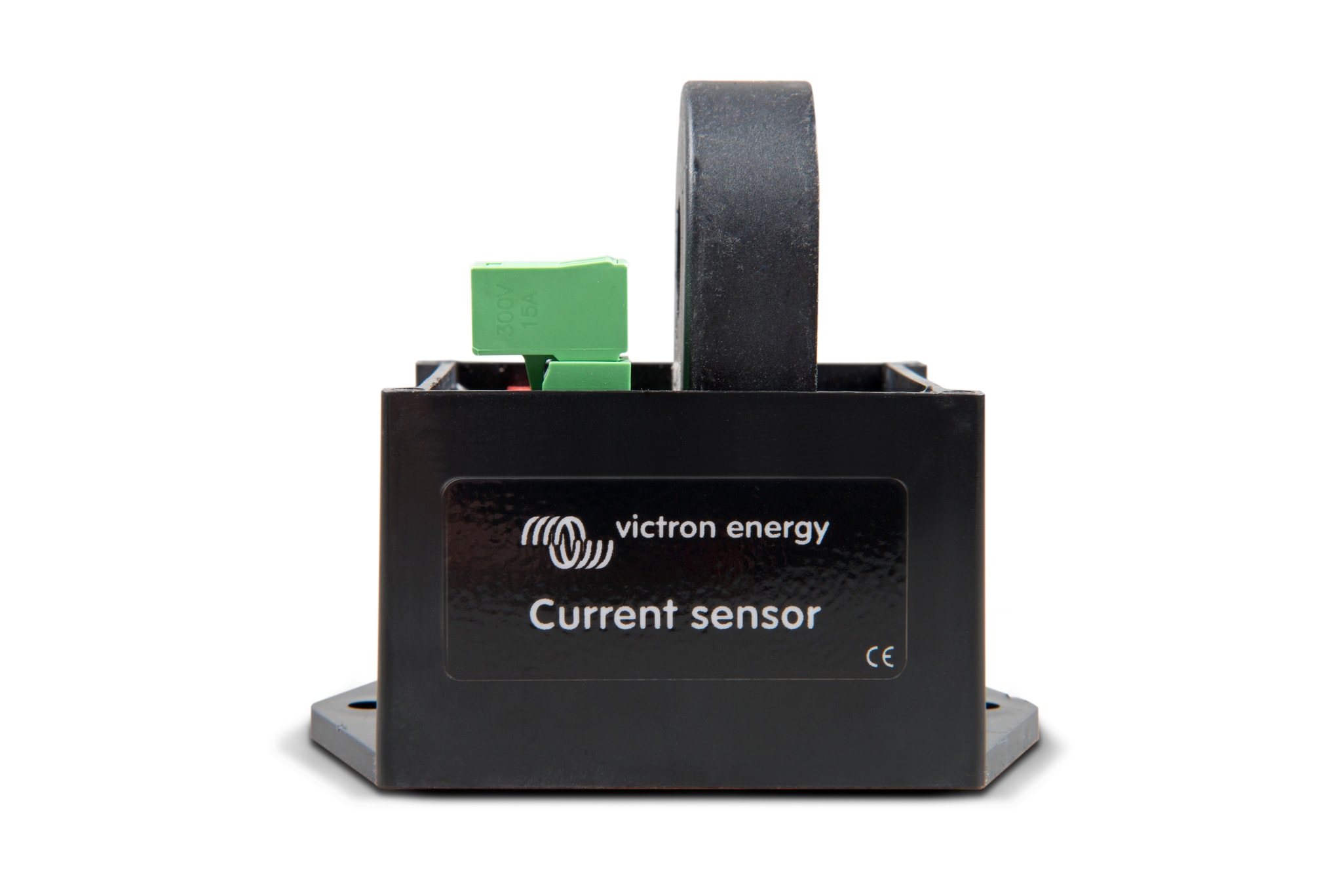
Description
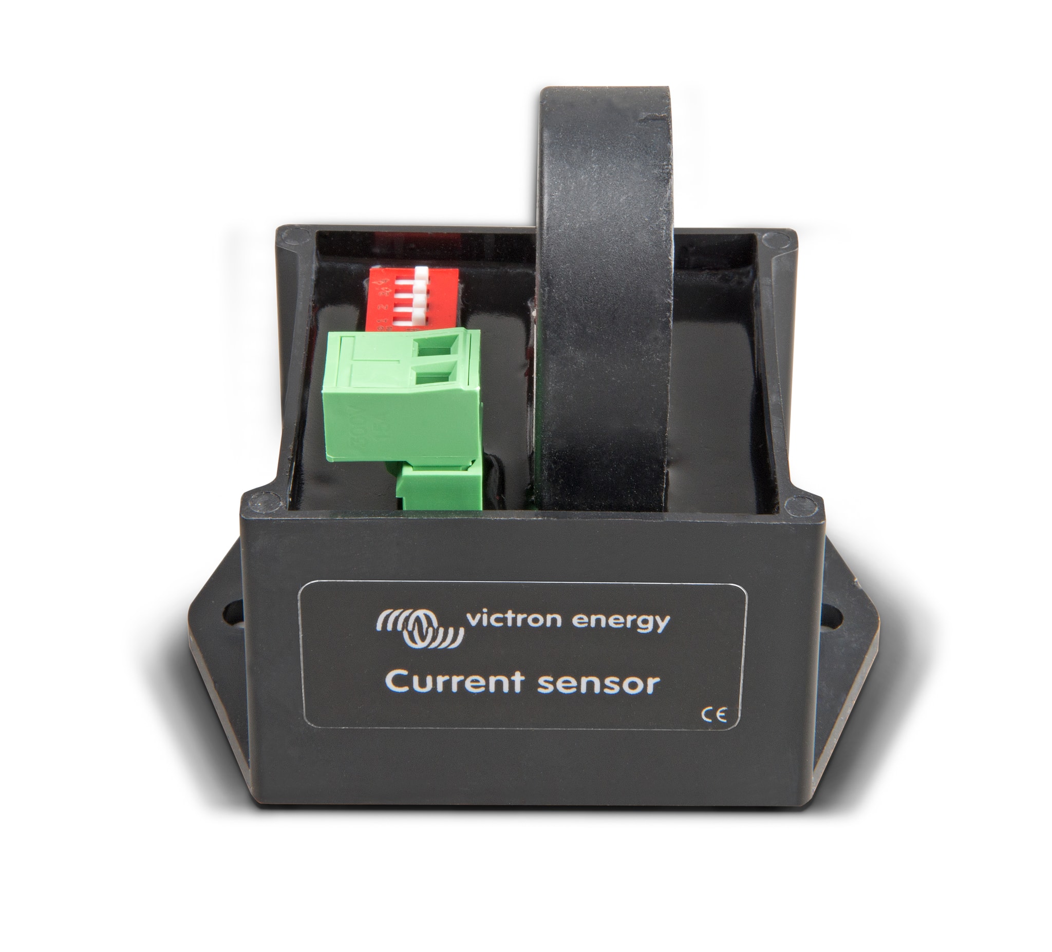
The Victron CSE000100000 AC Current sensor measures the AC current of a PV inverter, so solar production can be shown on a GX device and the VRM Portal. Combined with voltage measurements, it is used to calculate apparent power (VA) and energy (kWh). It is a simple external sensor that wires to a Multi or Quattro inverter/charger.
Features
- Installs by passing one of the PV inverter’s AC wires through the sensor.
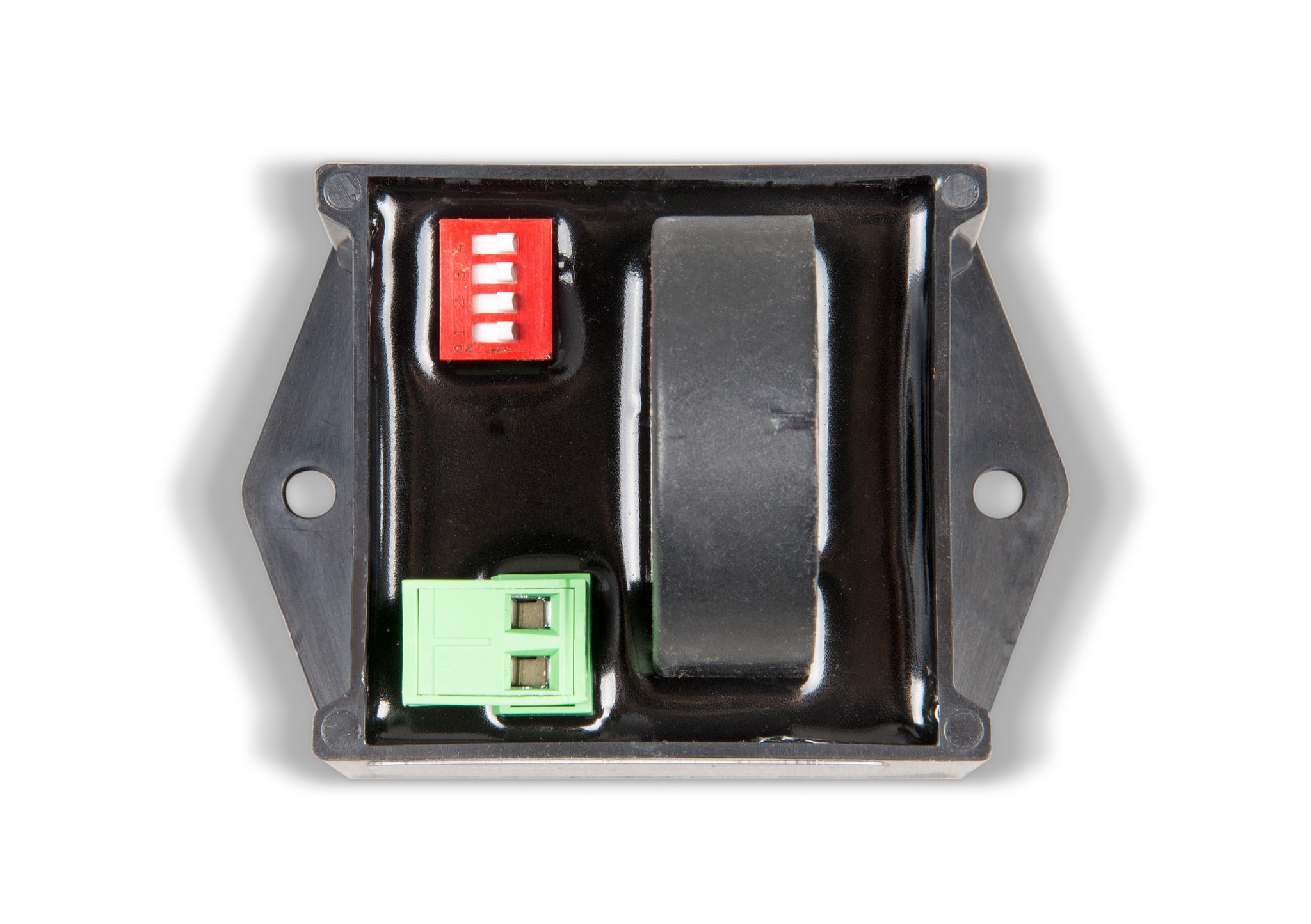
- Dipswitches set the power range to 1.5 kW, 3 kW, 5 kW or 7 kW. Choose the range equal to or higher than the highest expected power.
- Connects to the TEMP-sense input of Multi and Quattro models. The AUX input is suitable only on some hardware.
- Up to 9 sensors in one system. A multi-phase PV inverter needs one sensor per phase, wired to the Multi in the same phase.
- Protection category IP54.
- Readings appear on the GX device and the VRM Portal.
- Needs a Multi or Quattro with the newer microprocessor, identified by a 7-digit firmware version starting with 26 or 27.
Specifications
| Part number | CSE000100000 |
| Current type | AC |
| Power range | 1.5 kW, 3 kW, 5 kW, 7 kW (set with dipswitches) |
| Dipswitch setting for 1.5 kW | all off |
| Dipswitch setting for 3 kW | 1 |
| Dipswitch setting for 5 kW | 1,2 |
| Dipswitch setting for 7 kW | 1,2,3 |
| Max measured current | 8 A (1.5 kW), 16 A (3 kW), 25 A (5 kW), 30.5 A (7 kW) |
| Max input current | 9 A (1.5 kW), 18 A (3 kW), 30 A (5 kW), 40 A (7 kW) |
| Power step size, 230V AC (approx., depends on input voltage) | 9 W (1.5 kW), 17 W (3 kW), 30 W (5 kW), 35 W (7 kW) |
| Power step size, 120V AC (approx., depends on input voltage) | 4.5 W (1.5 kW), 8.5 W (3 kW), 15 W (5 kW), 17.5 W (7 kW) |
| Max number of sensors in one system | 9 |
| Protection category | IP54 |
Compatibility
Victron’s compatibility list names the supported MultiPlus, Quattro and Multi-G models and the input each one uses. The AUX input depends on hardware, so check the serial number list before using it.
- The Multi or Quattro needs the newer microprocessor: a 7-digit firmware version starting with 26 or 27. Older control boards start with 19 or 20 and are incompatible.
- Connect the Multi or Quattro to the VE.Bus port of the Color Control GX. Readout does not work on the VE.Can port with a VE.Bus to VE.Can interface cable.
- On MultiPlus-II hardware revision 0 to 8, the AUX input is on the RJ12 connector, pins 1 and 5. Later revisions have the AUX input as a normal terminal.
- Inverter/charger firmware must be 2xx or later. The GX device needs at least v1.30, and a more recent version is required.
- The Victron CSE000100000 should not be confused with the Current Transformer 100A:50mA accessory for MultiPlus-II, part number CTR110000500.